Installing the Accutroll System on 25HP Suzuki EFI
Complete mechanical installation guide for the Accutroll throttle servo on a 25HP Suzuki EFI outboard motor (kicker).
Table of contents
- Step 1: Gain Access to the Throttle Linkage
- Step 2: Disconnect the Pushrod
- Step 3: Remove the Stock Throttle Arm
- Step 4: Install the Accutroll Throttle Arm
- Step 5: Prepare the Bowden Cable Assembly
- Step 6: Attach the Cable to the Throttle Body
- Step 7: Install the Bowden Tube Guide Bracket
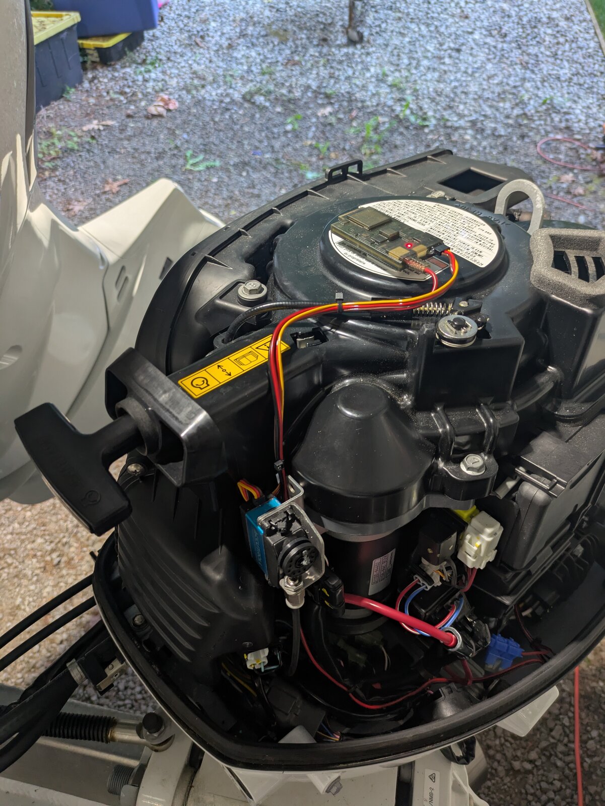
- Step 8: Prepare and Install the Servo Mounting Bracket
- Step 9: Mount the Servo
- Step 10: Prepare the Braided Cable at the Servo
- Step 11: Final Assembly
- Next Steps
- Need Help?
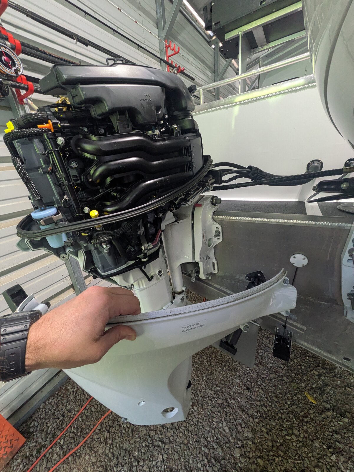
Step 1: Gain Access to the Throttle Linkage
Remove the engine cowling completely. Then remove the side cover/panel on the starboard side of the motor. This gives clear access to the throttle body and linkage area.
Step 2: Disconnect the Pushrod
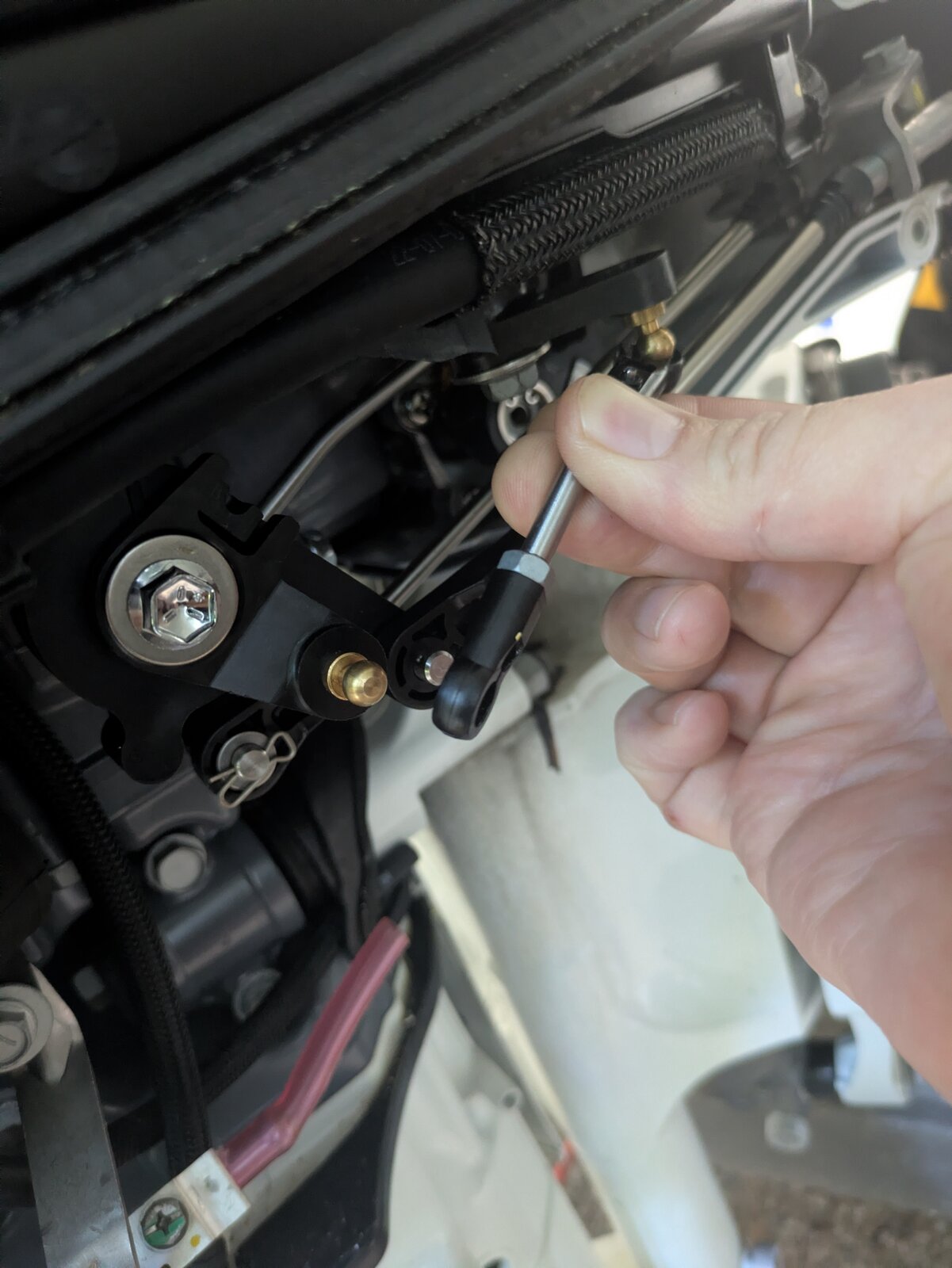
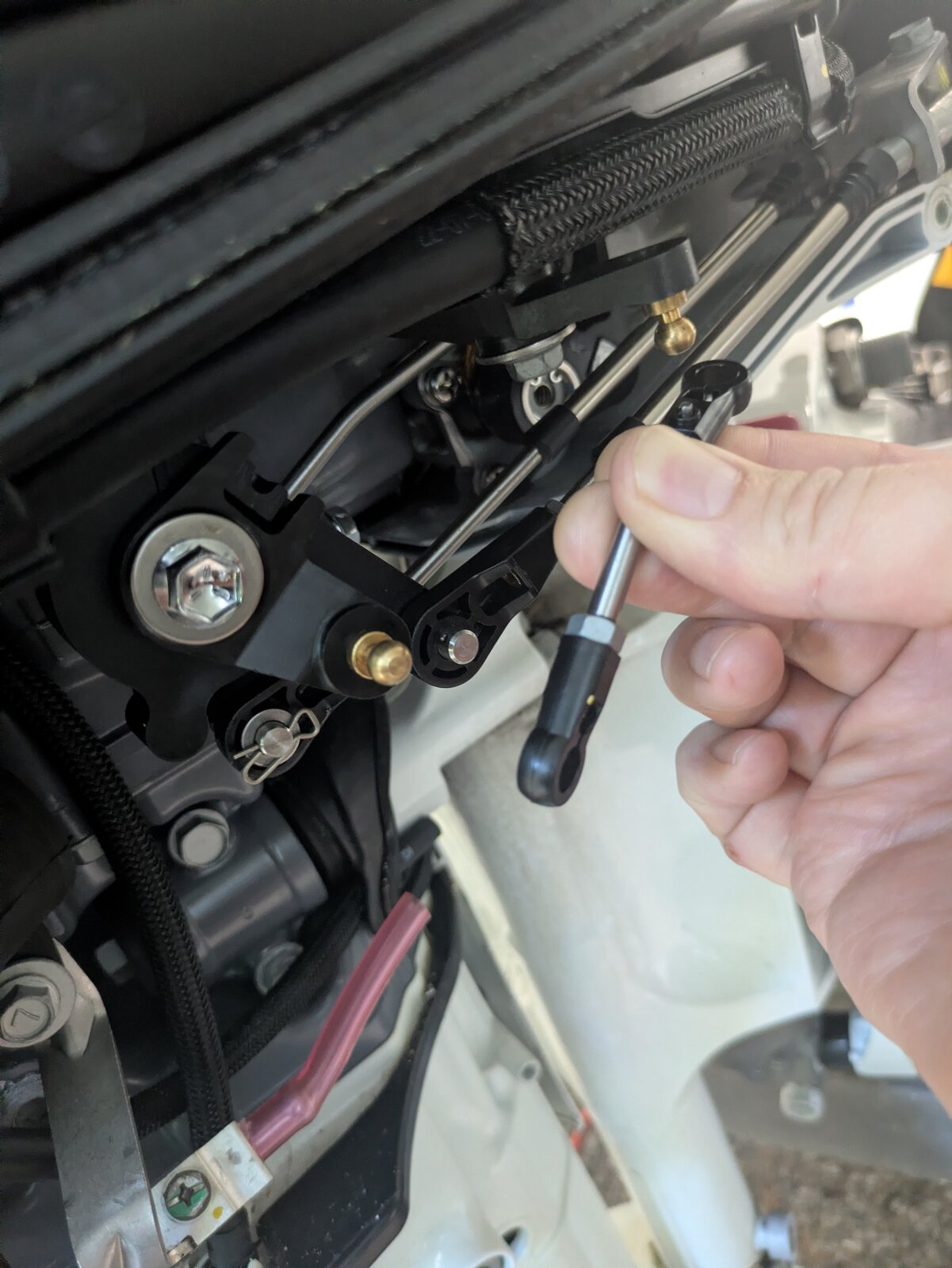
Locate the pushrod connecting the throttle linkage.
- Disconnect the aft (rear) end of the pushrod from the ball joint.
- Then disconnect the forward end from the ball joint.
Step 3: Remove the Stock Throttle Arm
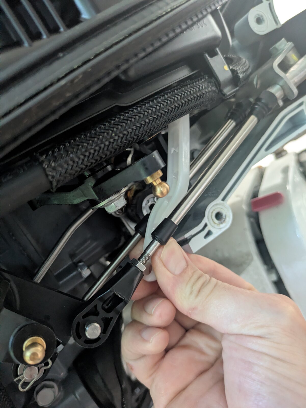
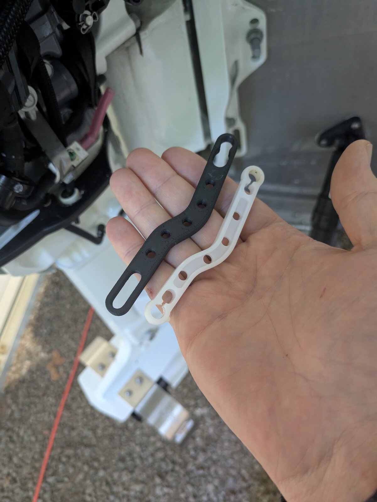
Disconnect the white plastic throttle arm from the two ball joints. Note the orientation. This arm will be replaced with the one included in the kit. The replacement arm has a slotted coupler on the aft end of the arm.
Step 4: Install the Accutroll Throttle Arm
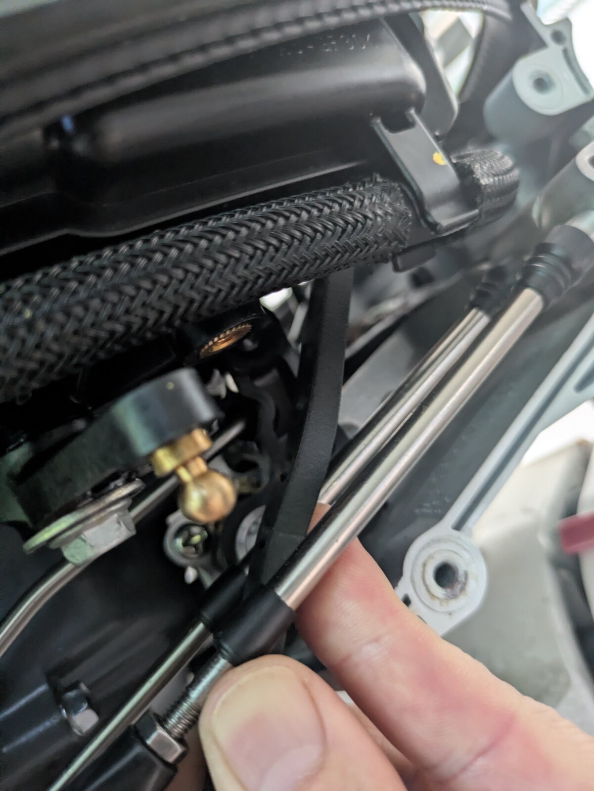
- Snap the static (non-slotted) end onto the throttle body first.
- Snap the slotted end over the ball joint.
Step 5: Prepare the Bowden Cable Assembly
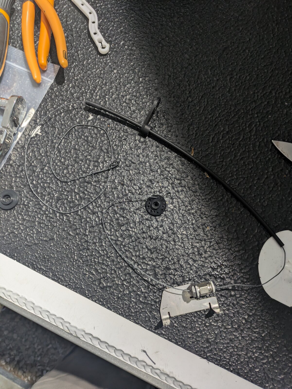
Lay out the Bowden tube and bracket assembly as shown.
Step 6: Attach the Cable to the Throttle Body
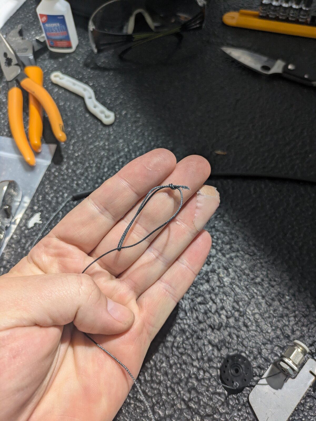
Create a loop in the end of the braided cable. Cinch the loop of the braided cable around the tab on the throttle body.
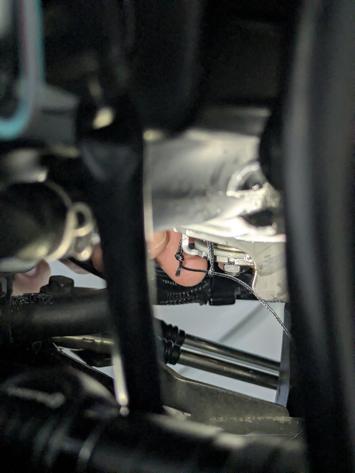
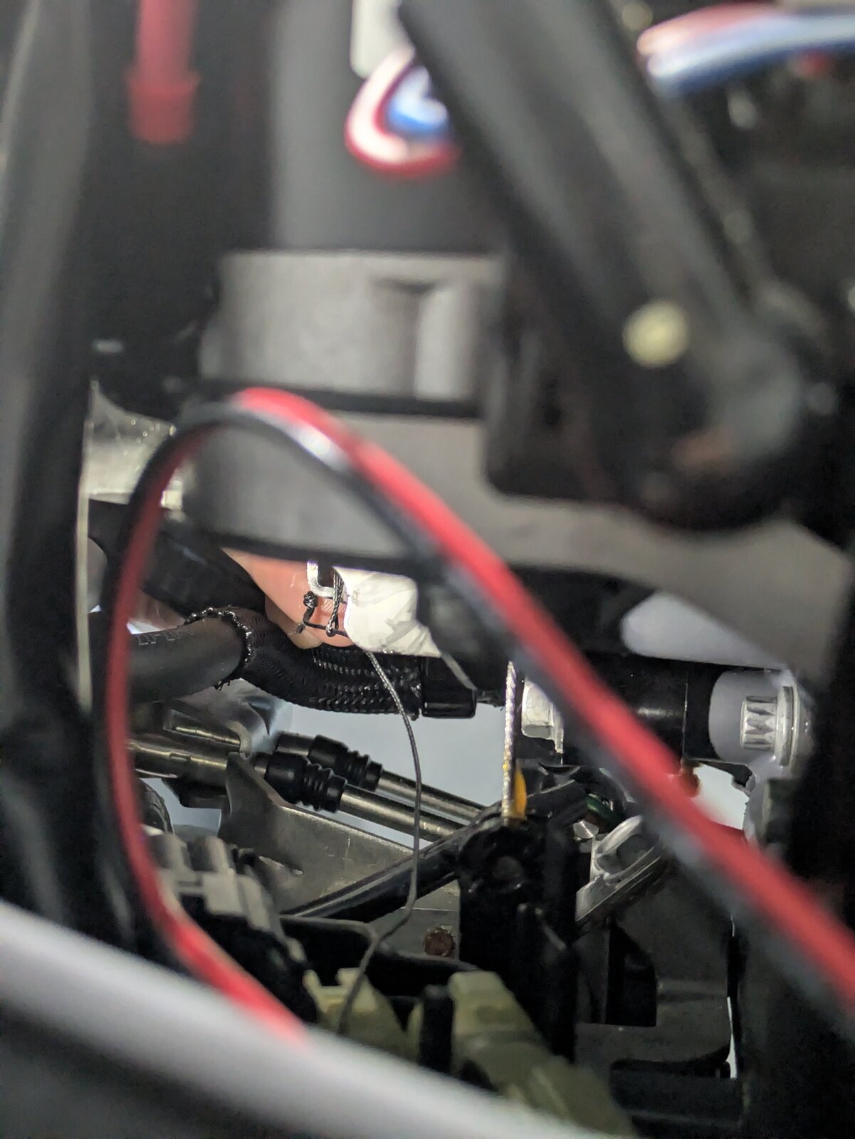
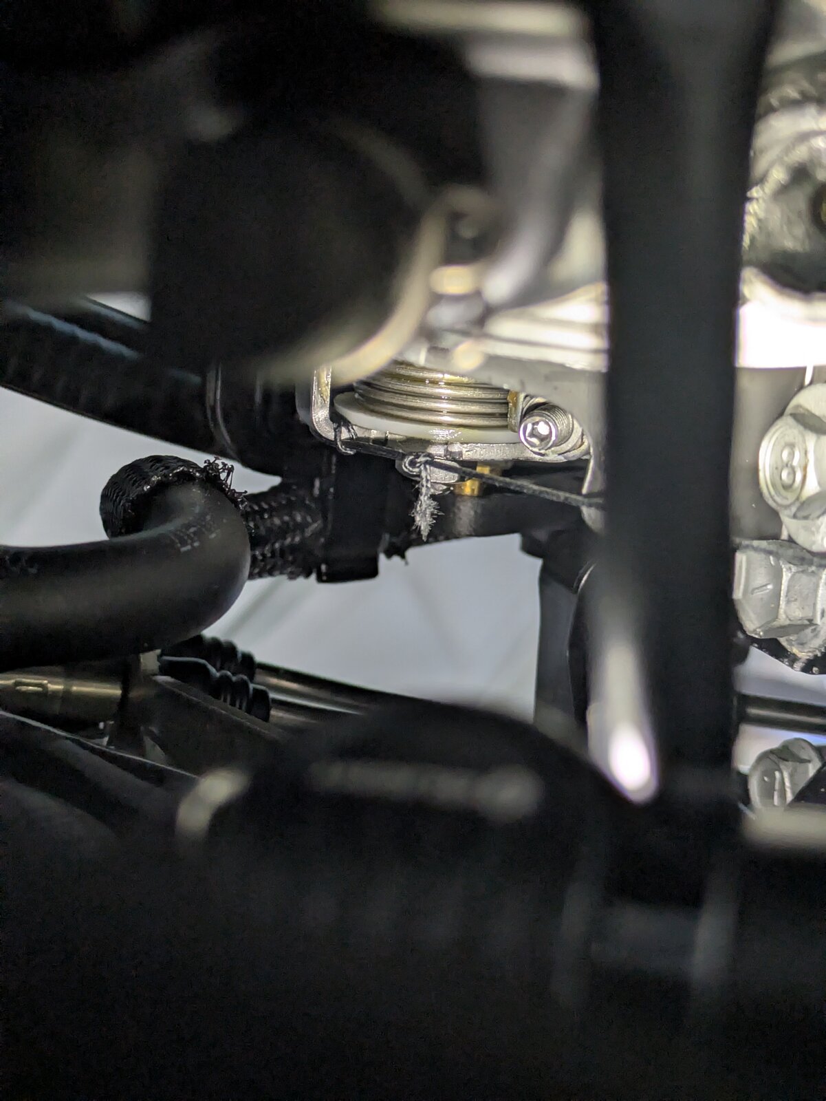
Step 7: Install the Bowden Tube Guide Bracket
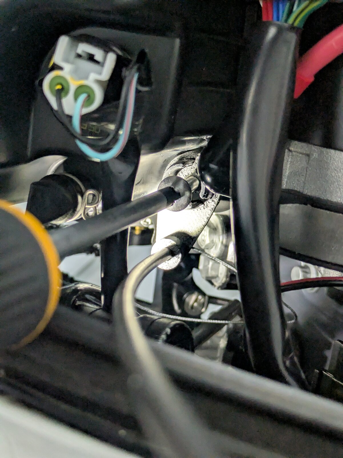
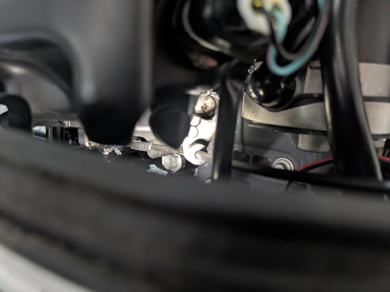
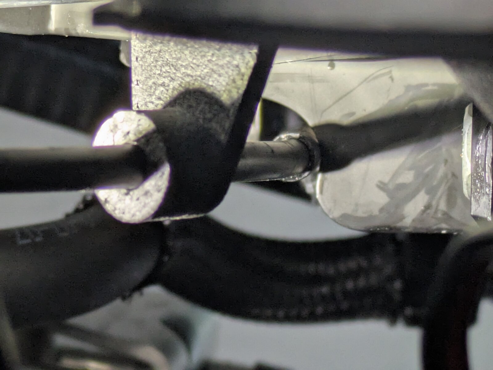
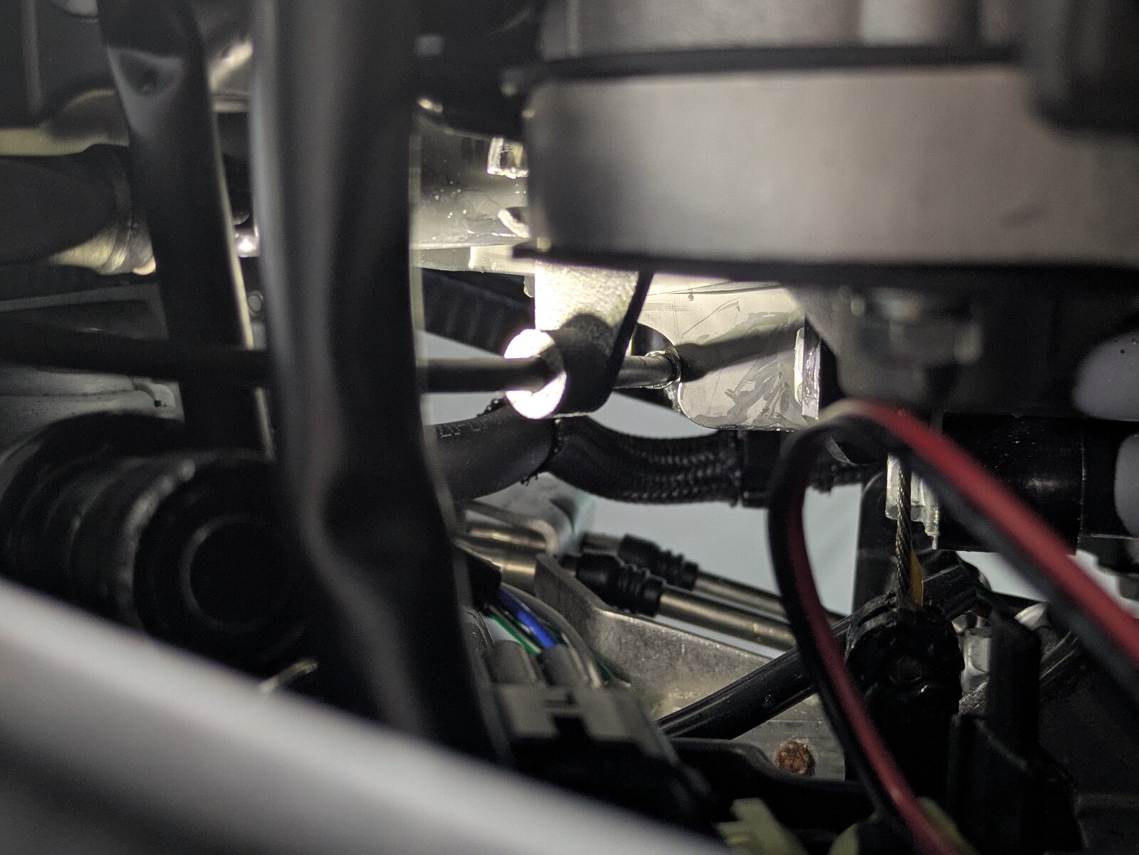
- Remove the existing screw at the location shown.
- Reinstall the screw, passing it through the Bowden tube guide bracket.
- Orient the far end of the Bowden tube so the end cap rests firmly against the edge of the guide bracket as shown.
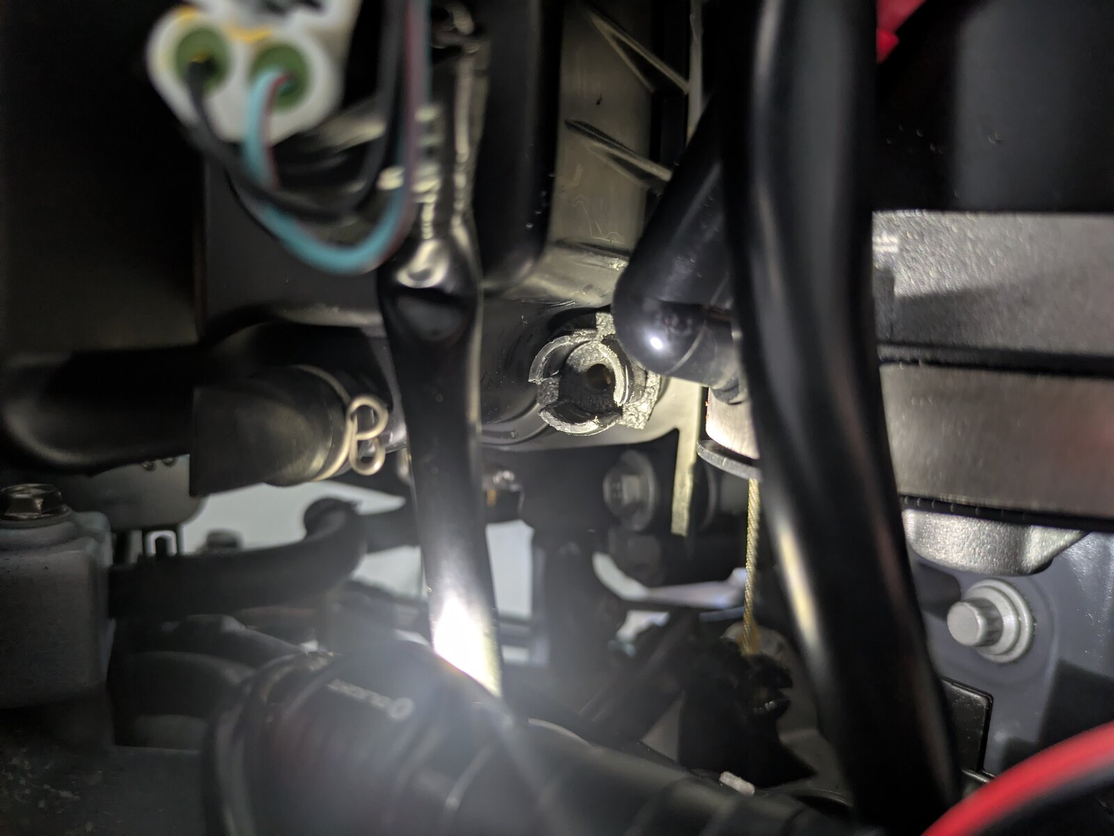
Step 8: Prepare and Install the Servo Mounting Bracket
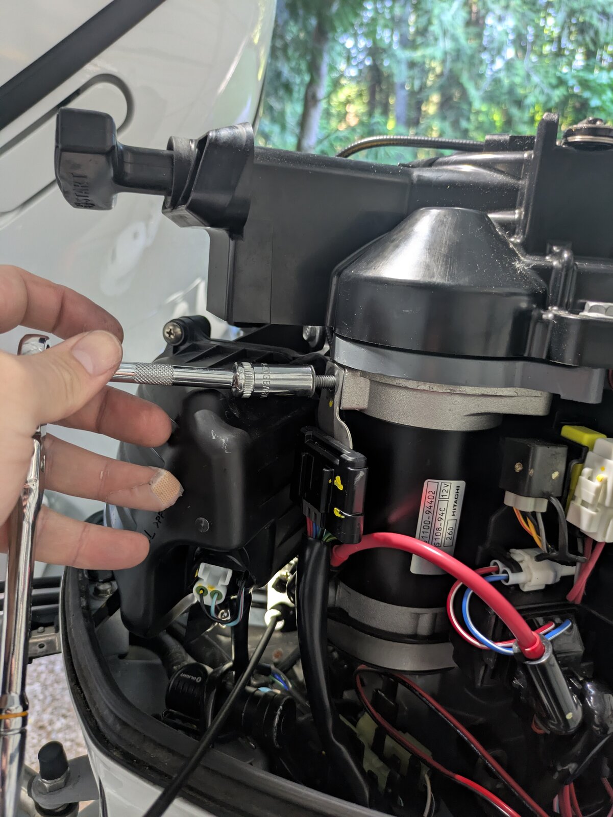
- Remove the bolt at the location as shown.
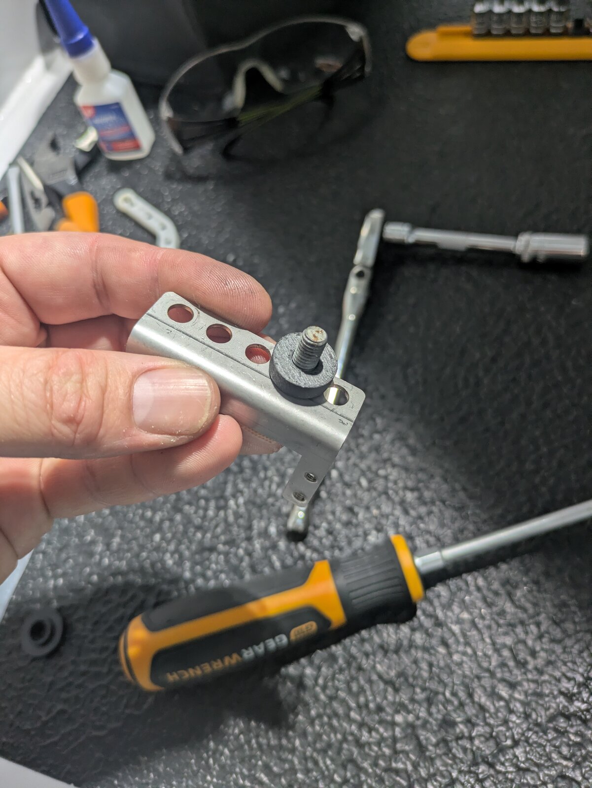
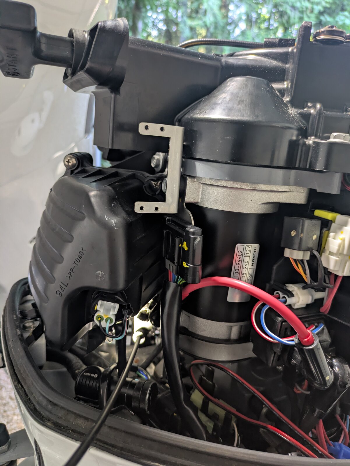
- Insert the bolt through the second hole of the Accutroll servo bracket.
- Add the supplied spacer.
- Reinstall the bolt to secure the bracket to the side of the starter motor.
Step 9: Mount the Servo
- Secure the servo using the supplied zip ties.
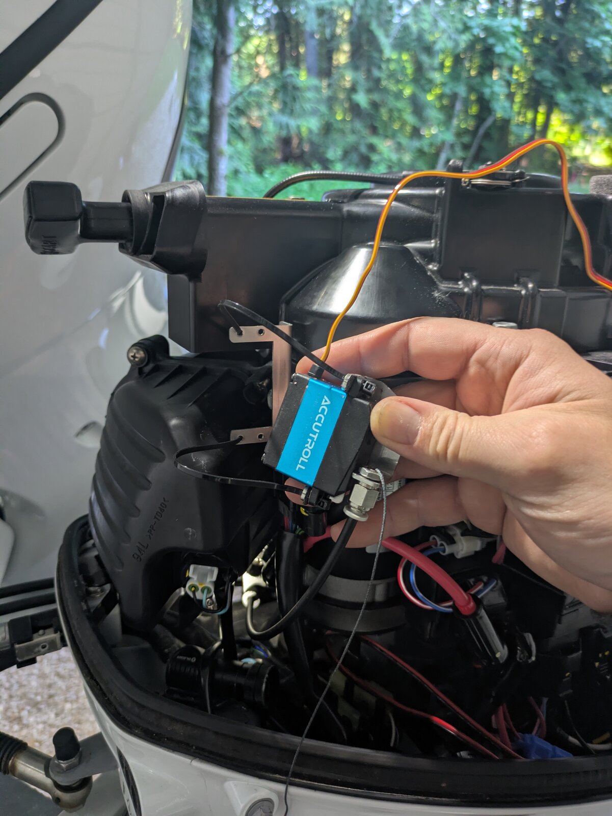
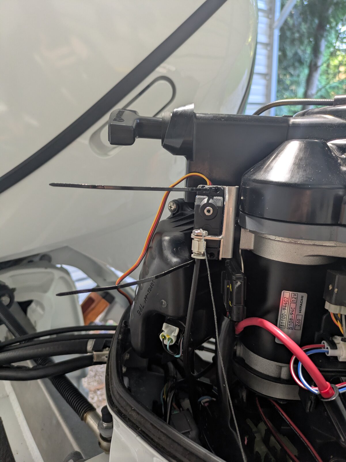
Step 10: Prepare the Braided Cable at the Servo
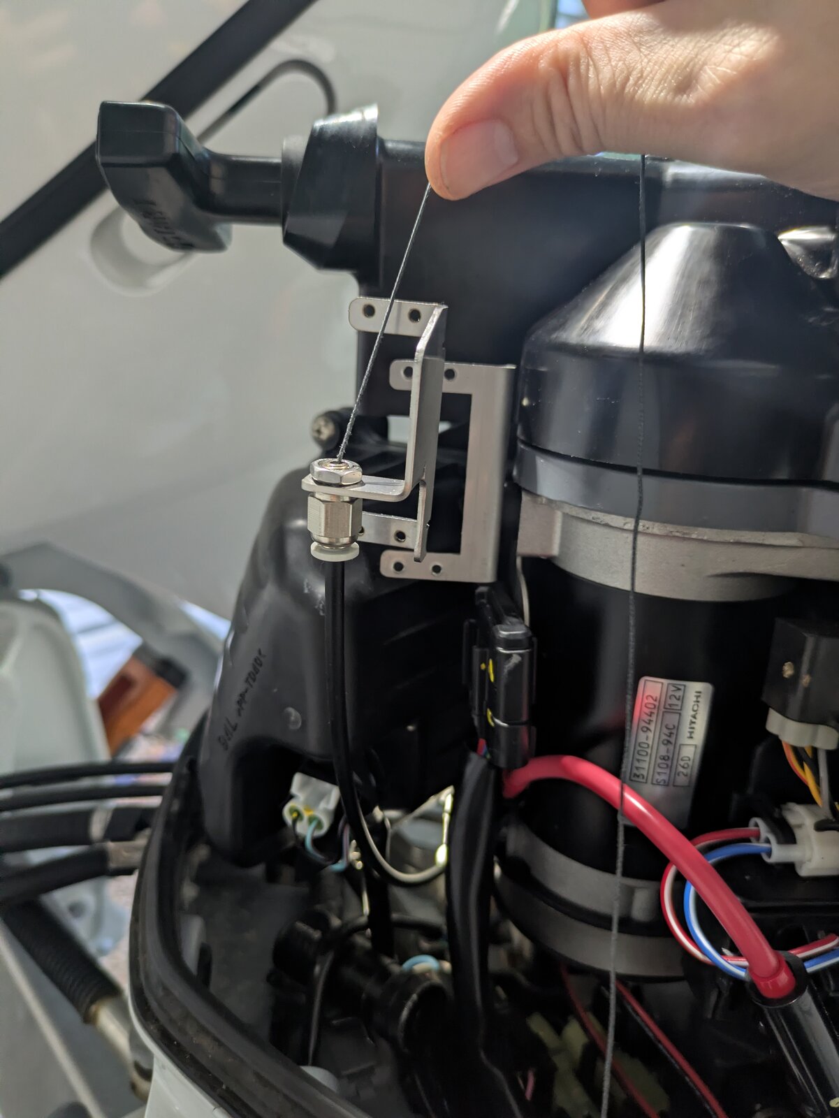
- Feed the free end of the braided cable through the hole of the round servo horn.
- Tie a large knot that will keep it from passing back through the hole.
- Snap the second half of the round servo horn/spool adapter into place.
- Coil the excess braid firmly onto the spool.
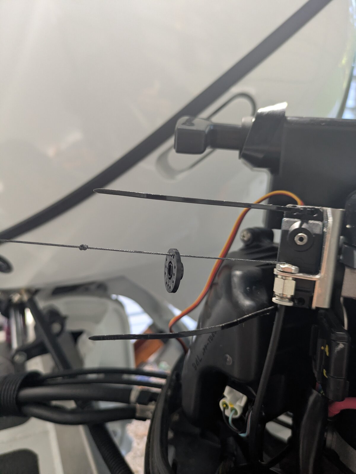
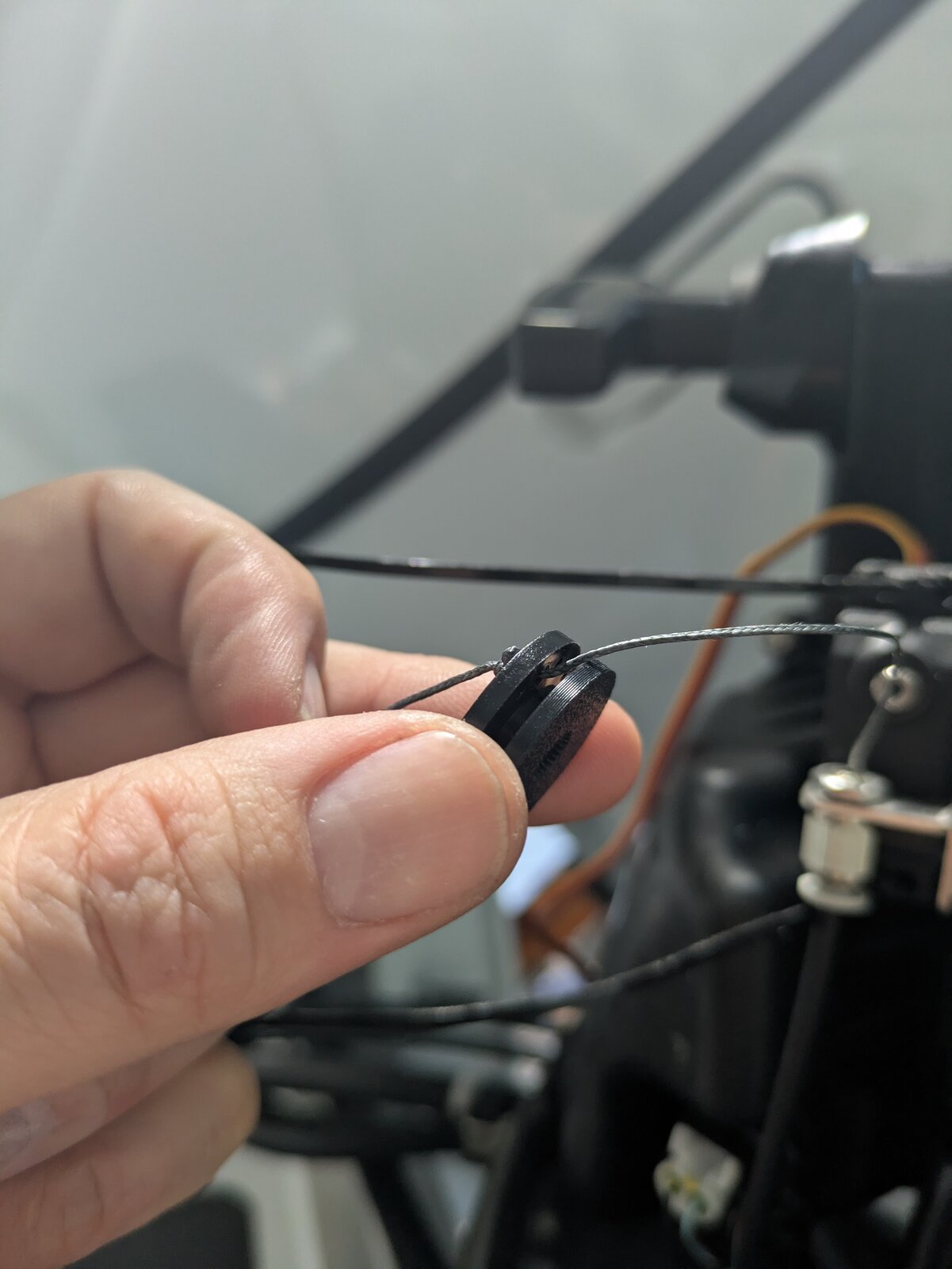
Do not attach the spool to the servo yet. Leave the round servo horn/spool adapter off the servo shaft. The servo must be mounted with the horn removed (see the main TCM Installation Guide). The cable will be secured to the horn during the calibration step later.
Step 11: Final Assembly
Reinstall the starboard side panel and the engine cowling. Verify that the throttle linkage moves smoothly by hand before proceeding with electrical connections.
Next Steps
After completing the mechanical installation:
- Proceed with TCM power wiring and mounting (see the main TCM Installation Guide).
- Connect the servo to the TCM.
- Mount the TCM using the supplied ALFA-LOK fasteners.
- Discover the device in the Accutroll app.
- Calibrate the servo sweep range.
Need Help?
- Email Support: support@accutroll.com
- Contact Form: accutroll.com/pages/contact